High availability through 3-in-1 monitoring

Years ago, a momentary voltage dip might have caused the lighting to flicker, but today it can paralyze entire businesses. Close monitoring is therefore essential. The faults can also be – literally – home-made. In the best case, defects can even be detected and rectified as they arise. To monitor the entire infrastructure, the user does not have to work with a large number of instruments. A single modern monitoring system can do this conveniently and reliably.
Highly automated production facilities, data centers, and continuous processing facilities (e.g. food, cable factories, paper production) require a reliable power supply – often even high availability, i.e. an availability of at least 99.9%. The many servers, monitors, storage media, and network components barely tolerate voltage dips or other deviations in power quality from the standard (e.g. EN 50160). However, a reliable power supply is not only necessary for information and communication technology, but also for infrastructure tasks such as air conditioning, fire prevention, EMC, safety technology, lighting, elevators, and drives.
3-in-1 monitoring for safety and efficiency
It is not surprising that in all these applications the demand for a secure power supply comes before ubiquitous energy efficiency. Continuous monitoring with appropriately integrated measurement technology for energy management, power quality, and residual current monitoring meets this need, as it serves both demands. In addition, residual current monitoring improves preventive fire protection. In practice, however, it is very time-consuming to record, evaluate, and document all measurement data. All of this must be done very quickly if, for example, an insulation fault is to be detected before the system fails.
That is why, Janitza, the specialist in digital measurement technology and energy supply monitoring systems, has developed its new UMG 512, UMG 96RM-E, and UMG 20CM series for monitoring on three levels (see section "Monitoring solutions in practice"). Together with GridVis® software and integrated alarm management, they combine solutions for three areas in a common system environment with just one measurement device per measurement point:
3-in-1 monitoring
- Energy management according to ISO 50001 (recording of V, A, Hz, kWh, kW, kVArh, kvar ...)
- Power quality monitoring (harmonics current, flicker, voltage dips, transients ...)
- Residual current monitoring (RCM)
This bundling of three different functions into a single measurement device has the great advantage that assembly, installation, and the rest of the infrastructure (current transformers, communication lines and equipment, database, software, analysis tools and reporting software ...) are only required once. Furthermore, all data is recorded centrally in a database and can be conveniently processed with just one software program. This not only saves direct costs for purchasing, but also simplifies the integration process: No interfaces between different systems are necessary, as it's just one system. This also reduces the effort required for training and familiarization, which in turn increases acceptance among the relevant electricians.
Report before failure
With the new system, Safari Lodge meets most of its energy demand with the solar power system, which produces a total of 300 kWp. 260 kWp rooftop systems have been installed on the carports and the employees' accommodation (image 1). On top of this, 40 kWp is produced by three dual-axis trackers (image 2). They feed the lithium-ion storage with a capacity of 1,027 kWh (image 3), which in turn supplies the grid-forming, bidirectional battery inverter. With a peak output of 250 kW at stable output voltage and frequency, it provides ample reserves for a 3-phase power supply. Even larger consumers, such as cooling systems, engines or the charging stations for the Land Cruisers, can be reliably operated using this system. The inverter and batteries are housed in a 20-foot energy container. It has been equipped with air-conditioning and an extinguishing gas system and was delivered fully wired.
A 150 kVA diesel generator is used for emergency power supply. The generator was upgraded from a stand-by generator to a generator that can be controlled remotely and is suitable for parallel operation. However, it is only used in exceptional cases. The system runs on almost 100% renewable energy. In addition, the regional energy supplier's single-phase line can also be connected.
Universal RCM tool: Greater safety, higher system availability, lower fire hazard
Energy sources are plentiful at the lodge: Sun, the local grid, the battery, diesel as a buffer... There is no risk of the guests suddenly sitting in the dark or the Land Cruisers not running - provided the energy flows in the right directions. This is taken care of by UPP, short for Universal Power Platform. This energy management system was developed by Dhybrid specifically for smart grid control. The intelligent control platform provides full transparency and control over the whole energy system. It monitors all the network parameters as well as the power generators' active and reactive power reference values. This means that the system can be operated automatically.
Unlike many conventional microgrids, where either the diesel or the photovoltaic system runs at any one time, the Dhybrid UPP can control different generators simultaneously and in coordination with each other. This means that the diesel generator only needs to be switched on during periods of exceptionally high energy consumption or during bad weather. Tom Fricke, who manages the energy storage and sales division at Dhybrid, pointed out another advantage: "Our system is open to all technologies, which means we can connect equipment from a wide range of manufacturers. Since we can use all components, we can act very proactively. This is true, for example, for the service life of batteries. Different operating conditions cause them to age faster or slower. Because we know how the load or photovoltaic generation evolves throughout the day, we can optimize the operating strategy to make the battery last longer.”
Realtime monitoring and remote maintenance of the network are carried out by VPN using a SCADA system from Dhybrid. Additionally, the UPP offers access to historical data, reports and dashboards through a web portal.

But RCM can do even more, namely reduce the risk of fire! A residual current triggered by defective insulation can be treacherous. The current level is determined by the power of the supply network, the insulation fault resistance, and the grounding resistance. If the current flow is sufficiently high (with a full ground fault or correspondingly low-resistance short circuit), the upstream protective device will disconnect the electrical consumer from the grid. However, if the residual current is too low, the protective device will not trip. If the registered fault power exceeds a value of approx. 60 watts (approx. 261 mA at 230 V), there is a risk of fire. Residual current monitoring therefore also serves to prevent fires. The next section explains how RCM works in detail.

RCM – How it works
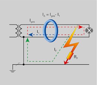
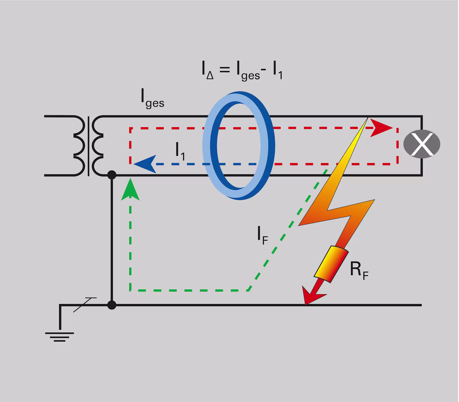
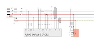
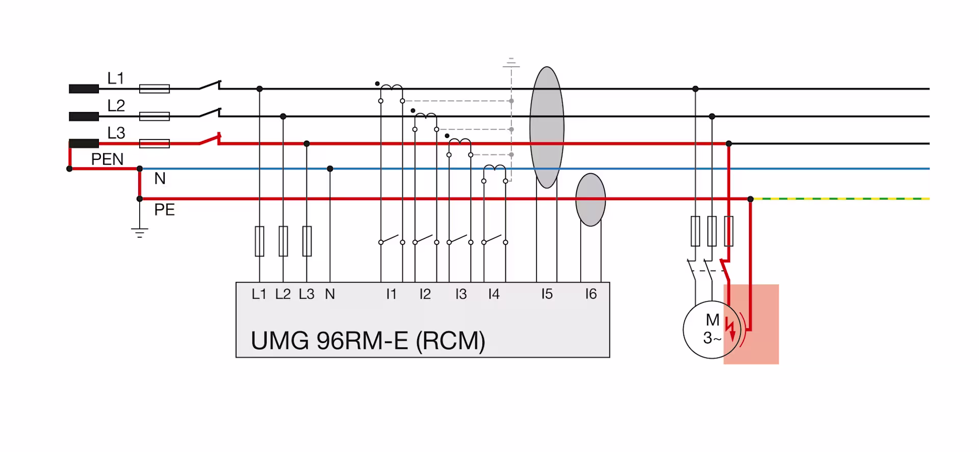
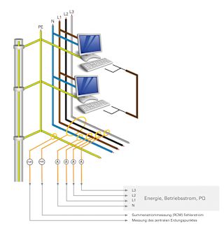
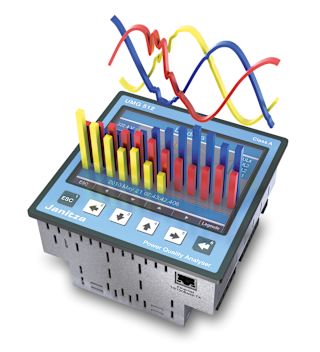
The basic operation of the residual current principle is shown in Image 2. The phase and the neutral conductor of the outgoing circuit to be protected are routed through the summation current transformer, the protective conductor is excluded. The image shows a simplified circuit for a better overview. In practice, all three phases and the neutral conductor run through the summation current transformer. When the system is in the fault-free state, the summation current is zero or close to zero (within the tolerance range), so that the current induced in the secondary circuit is also zero or close to zero. If, on the other hand, a residual current flows to ground in the event of a fault, the current difference in the secondary circuit causes a current that is detected and evaluated by the RCM measurement device (Image 3).
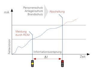
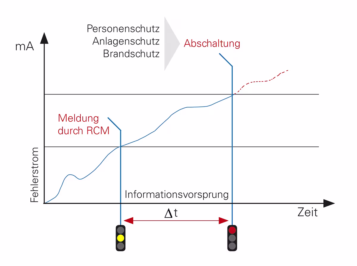
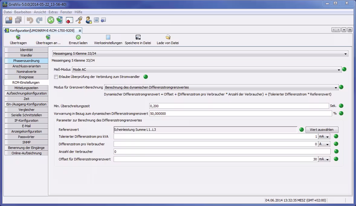
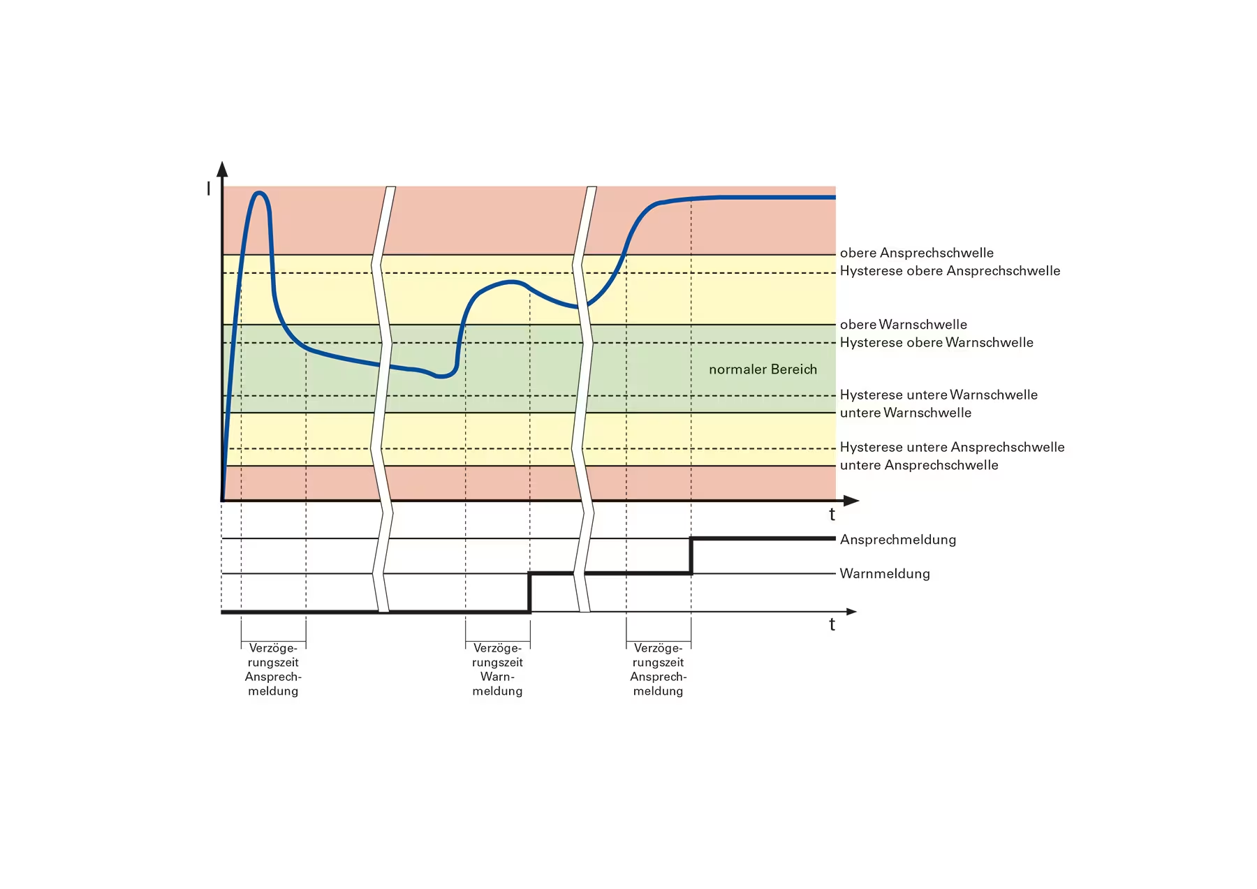
Modern RCM devices allow different limit value settings (Image 4). A static limit value has the disadvantage that it is either too large at partial load or too small at full load, i.e. there is either insufficient protection or false alarms occur, which can have a negative effect on the attention of the monitoring personnel in the long term. For this reason, it is recommended to use RCM measurement devices with dynamic limit value adaptation. In this case, the residual current limit value is formed on the basis of the current load conditions and is therefore optimally adapted to the load in question (Image 5).
By parameterizing (i.e. defining the typical residual current in the "GOOD" state) the system in the new state and continuous monitoring, all changes in the system state can be identified from the time of initial commissioning. This can also be used to detect creeping residual currents.
New technology, new sources of error
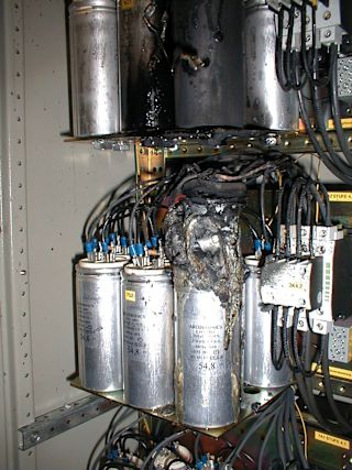
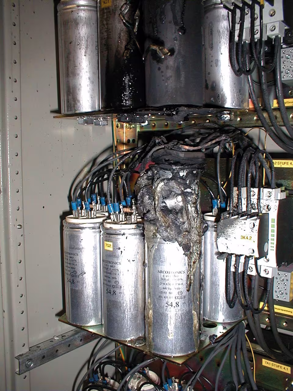
Collapsing polypropylene phase-shifting capacitors are an example of "modern sources of error". These are used to compensate for reactive currents, such as those caused by three-phase motors.
Paradoxically, a fault is therefore caused by a device that is actually intended to improve the energy supply. The PP windings of these capacitors often melt due to overload or overtemperature. The melting mass then causes a high-impedance ground fault. Such ground faults cannot be switched off by conventional protective measures (NH fuse, circuit breaker). The continuous residual current usually leads to a saturated short circuit in the medium term and can then pose a considerable fire or safety risk under certain circumstances (Image 6). Residual current measurement detects such faults and allows rapid countermeasures to be taken. This prevents costly and dangerous system failures.
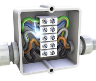
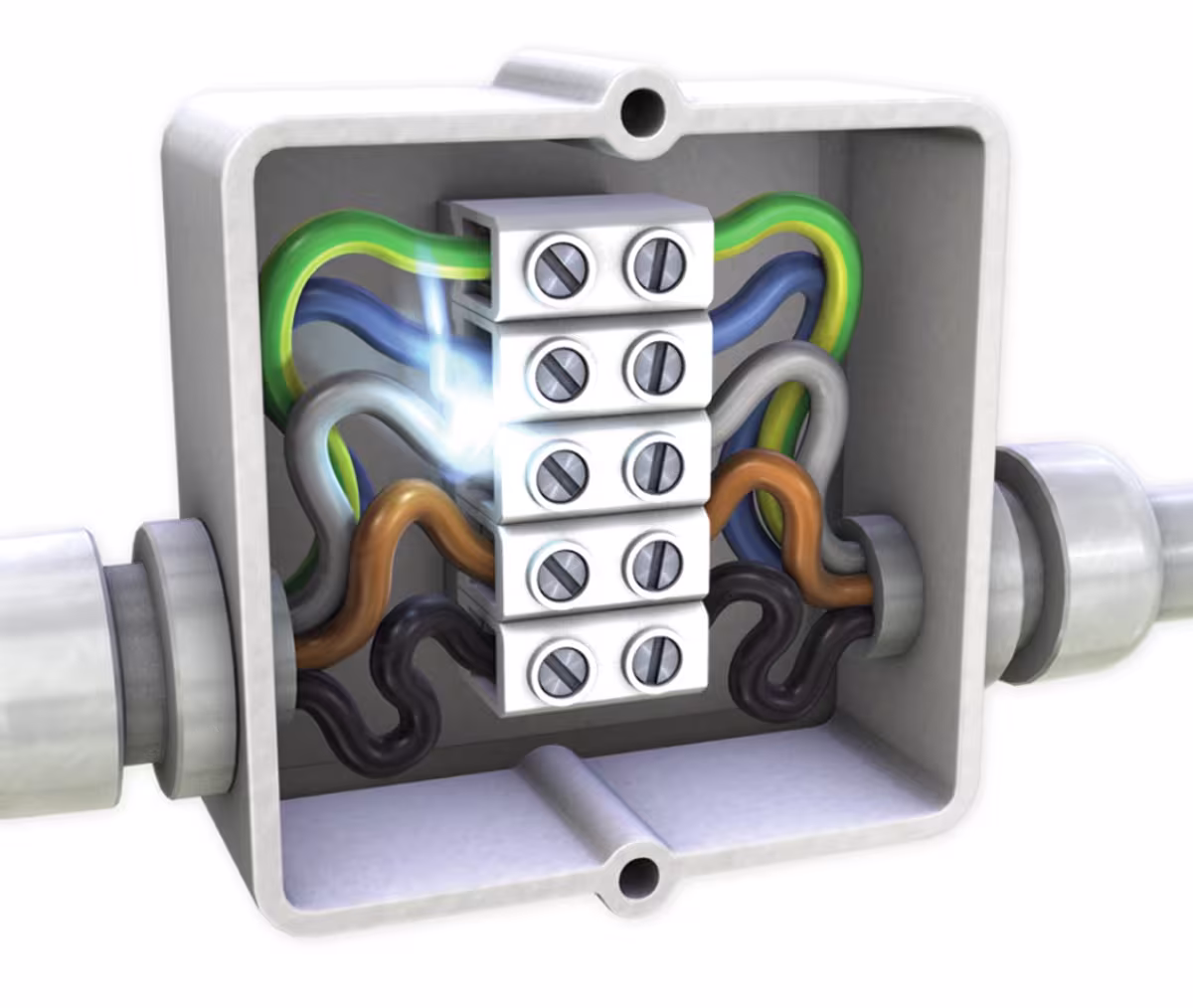
Faults often occur during installation, such as impermissible connections between the N and PE conductors. Sometimes the two are simply interchanged. Image 7 shows a typical connection fault, which can easily result in a residual current of 5000 mA. With RCM, such faults are detected immediately during the installation phase and reported via the alarm management system.
Another, more novel source of interference is a large number of single-phase loads, such as switching power supplies for servers in data centers or PCs in office buildings. They cause a high proportion of 3rd harmonics currents. These harmonic components have the major disadvantage that they are superimposed on the neutral conductor instead of canceling each other out via the transformer windings. The N conductor may be overloaded. Integrated measurement devices, such as the UMG 96RM-E, allow comprehensive monitoring of all phases and can therefore report excessive neutral conductor currents in good time.
In this context, it is also important to mention the safety regulations of the VdS (Association of Property Insurers) for electrical systems up to 1000 volts:
"VdS 2046: 2010-06 (11) 3.2.4 In order to increase safety in electrical installations in which numerous non-linear consumers (such as frequency converters, phase angle control systems, e.g. in lighting systems) are operated, the current in the neutral conductor must be measured regularly, e.g. once a year, and also after significant changes to the electrical installation or the type and number of electrical consumers. If the safety of the system is endangered by excessive harmonics currents, measures must be taken to protect against harmonics in accordance with the publication "Low-noise electrical installation" (VdS 2349)."

The challenge of high availability
IT technology in itself already places high demands on the supply. However, applications in which data loss simply must not occur are particularly critical. BITKOM, for example, writes in its guide "Operationally Secure Data Centers" as follows: "Data centers pose the highest availability requirements. Accordingly, the energy supply must be ensured on a sustainable basis. It is almost self-evident that the power supply of the data center itself and all areas in the same building to which data cables run must be designed as a TN-S system. Continuous self-monitoring of a "clean" TN-S system and the connection of messages to a permanently manned point, e.g. the control center, are absolutely essential for safe operation. The electrician then recognizes when action is needed via appropriate messages and can prevent damage through targeted service measures."
Janitza’s solution implements the safety criterion "RCM residual current monitoring" of such an EMC-optimized TN-S system (Image 8).
Reduce inspection costs with RCM
Periodic inspections, such as those prescribed by BGV A3 – Electrical systems and equipment, are time-consuming and therefore expensive. RCM monitoring systems can reduce these inspection costs and still ensure greater safety. Fixed electrical installations and equipment are considered to be permanently monitored if they are continuously maintained by qualified electricians and tested by means of metrological measures during operation (e.g. monitoring of insulation resistance). Continuous RCM measurement enables monitoring systems to ensure the required continuous testing.
Importantly, RCM makes the cost-intensive measurement of insulation resistance at least partially superfluous and allows continuous testing of the insulation properties. For conventional insulation measurement, the fixed installation or consumer must be switched off and the neutral conductor disconnected. In addition, there is a risk that sensitive electronic components may be damaged by the high test voltage of the insulation measurement. The inspection severity and scope can be reduced by continuous monitoring. However, this must be determined on an application-specific basis. Agreements with the operator, or in some cases experts and/or the employers' liability insurance association are absolutely essential for this.
It should be expressly mentioned at this point that the following work must be carried out despite continuous RCM measurement:
- Visual inspection for externally visible defects
- Protective measures and switch-off conditions
- Loop resistances and testing the continuity of protective conductors
- Function test
Association of Property Insurers insists on RCM
The VdS has the following to say about harmonics current/setting up the power supply system: "In power supply systems with PEN conductors, operational currents flow throughout the grounding and equipotential bonding system, which can cause damage (see section 3.3). TN systems should therefore be planned as TN-S systems for new electrical installations. Conversion to a TN-S system is recommended for existing TN-C systems. TN-S systems should be implemented from the infeed (transfer point) wherever possible, and must be monitored by a residual current monitor (RCM) in order to ensure the functionality of a TN-S system in the long term (no conductor short circuit between N and PE conductor, swapping of N and PE conductor). if the set response value is reached, a perceptible visual and audible error message must be issued so that the faults can be rectified immediately. For the message to be successful, it should be posted at a manned location if necessary. If no connection is made, the faulty circuit must by definition be disconnected ..."
Elsewhere, in the safety regulations for electrical installations up to 1000 volts, the VdS stipulates:"VdS 2046: 2010-06 (11) 3.2 Maintaining the proper condition 3.2.3 In order to ensure safety in electrical installations in the long term, if insulation resistance measurements cannot be carried out due to local or operational circumstances, alternative measures must be taken. Such measures are described in the publication "Protection in the event of insulation faults" (VdS 2349)."Permanent RCM monitoring is an adequate alternative measure here.
Energy measurement and standard electrical parameters
RCM plays a dominant role in installation monitoring with the Janitza system. Nevertheless, other points should not go unmentioned: In addition to a secure energy supply, energy efficiency is playing an increasingly important role. The adoption of the ISO 50001 standard was a milestone in this respect. ISO 50001 is the standard that governs the introduction of an energy management system, the focus here being on the term management system. Based on other management systems such as ISO 9001 or ISO 14001, this is a methodology for setting goals, implementing them systematically, and eliminating the factor of chance as far as possible. In this context, the term "goal" should rather be understood under the motto "the journey is the goal". An example of this is the resolution passed by the Council of IT Commissioners in February 2013: (page 2, resolution no. 2013/2, point 2)
"The IT Council continues to aim for a high proportion of continuous measurements by the end of 2013 and asks the departments to continue to promote the use of permanent measurement devices, taking into account the principle of economic efficiency." With all its UMG measurement devices and electricity meters, Janitza offers the option of recording and logging standard electrical parameters as well as power and energy consumption (Image 9).
Monitoring power quality
RCM and the requirements of Bitkom and the Association of Property Insurers were dealt with in the first two parts. The last point related to 3-in-1 monitoring is power quality. Reliable operation of modern plants and systems always requires high supply reliability and good power quality. But in modern energy supply, a large number of single-phase and three-phase, non-linear consumers are used, from industrial networks to office buildings. This includes lighting technology, such as light controllers for headlamps or energy-saving lamps, numerous frequency converters for heating, air conditioning, and ventilation systems, frequency converters for automation technology or elevators, as well as the entire IT infrastructure with the regulated switching power supplies typically used. Inverters for photovoltaic systems (PV) and uninterruptible power supplies (UPS) are also widespread today.
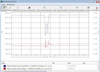
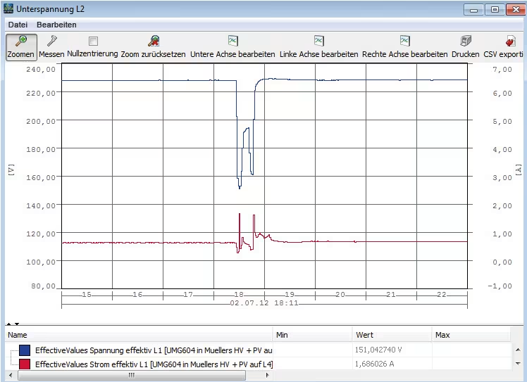
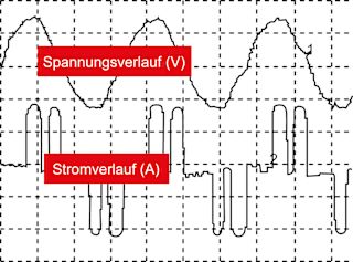
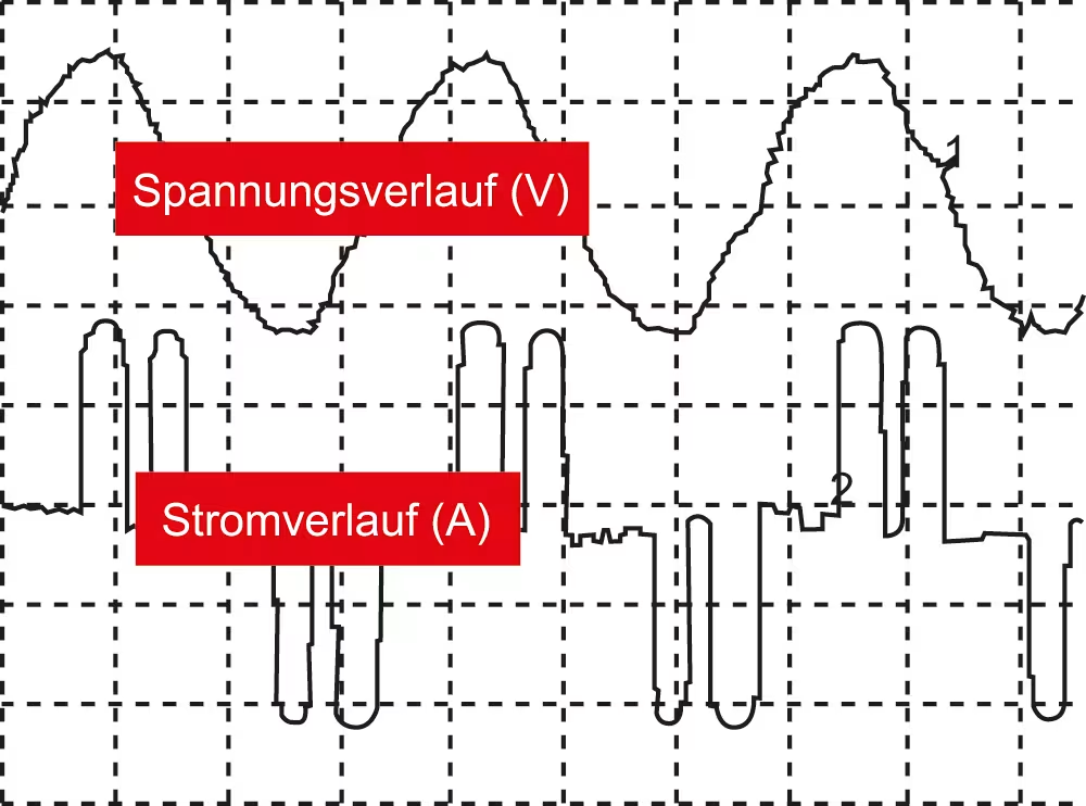
All these non-linear electrical loads cause more or less large grid distortions, with a distortion of the originally "clean" sinusoidal shape. This also distorts the current and voltage waveforms accordingly (Image 10 and Image 11).
The load on the grid infrastructure caused by electrical and electronic consumers with grid distortions described above has increased significantly in recent years. Depending on the type of generation system and equipment (grid feeder with inverter, generator), grid rigidity at the connection point and the relative size of the non-linear consumers, different grid distortions and interference occur. For secure power supplies in data centers, the power quality must comply with EN 61000-2-4 (class 1).
With a wide range of UMG measurement devices, Janitza offers the possibility of recording and analyzing the various parameters of power quality. Standardized power quality reports in the GridVis® software (e.g. for EN 50160, EN 61000-2-4, and ITIC: "CBEMA curve") allow reports to be generated for common standards virtually at the touch of a button.
Monitoring solutions in practice
The goal with 3-in-1 monitoring solutions, an integrated measurement of energy, power quality, and RCM, requires the measurement of all conductors (L1, L2, L3, N) + CGP (central grounding point) + RCM with a single measurement device.
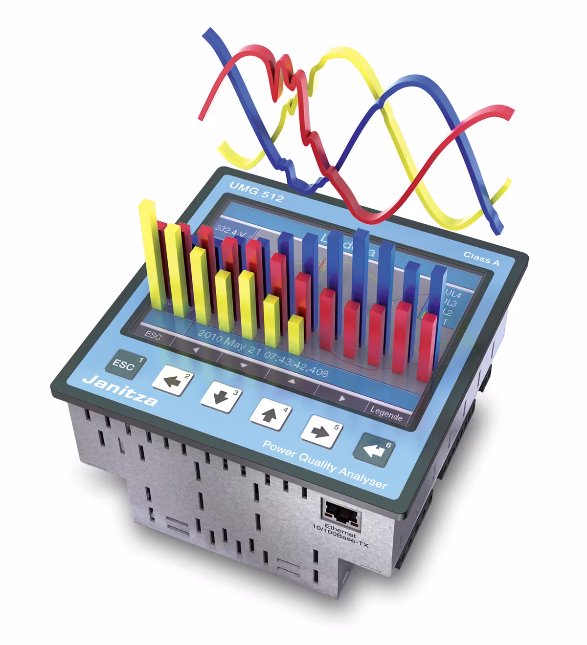
A powerful measurement device with 6 measured current inputs for 3-in-1 measurement is the UMG 96RM-E for intermediate distributors or the UMG 512 for main nodes and CGP from Janitza. These IP-based measurement devices can be easily integrated into existing communication networks via Ethernet. Numerous IP protocols, an onboard homepage, and SNMP protocols make work easier for administrators.
The 20-channel UMG 20CM is ideal for complex electrical installations with a large number of monitoring points. These measurement devices can capture, continuously record and analyze residual and operating currents in any combination using the corresponding measuring current transformers (e.g. CT-6-20).
Special residual current transformers with practical custom designs also allow cost-effective retrofitting of existing systems without having to switch off electrical consumers.
Alarm in the right place
Alarms must not go unheard. An acoustic signal from the switchboard cabinet in the NH distribution board is of little use in the control room.
By integrating RCM measurement devices into the GridVis® software with its extensive alarm management reporting options, it can be ensured that the message reaches the right recipient quickly. With any escalation level and logbook function, the monitoring control center has all the tools it needs for efficient monitoring. This enables the responsible electrician to detect and assess any residual current increases as quickly as possible and initiate maintenance measures if necessary.
Vagrant currents disturb the EMC
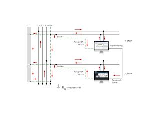
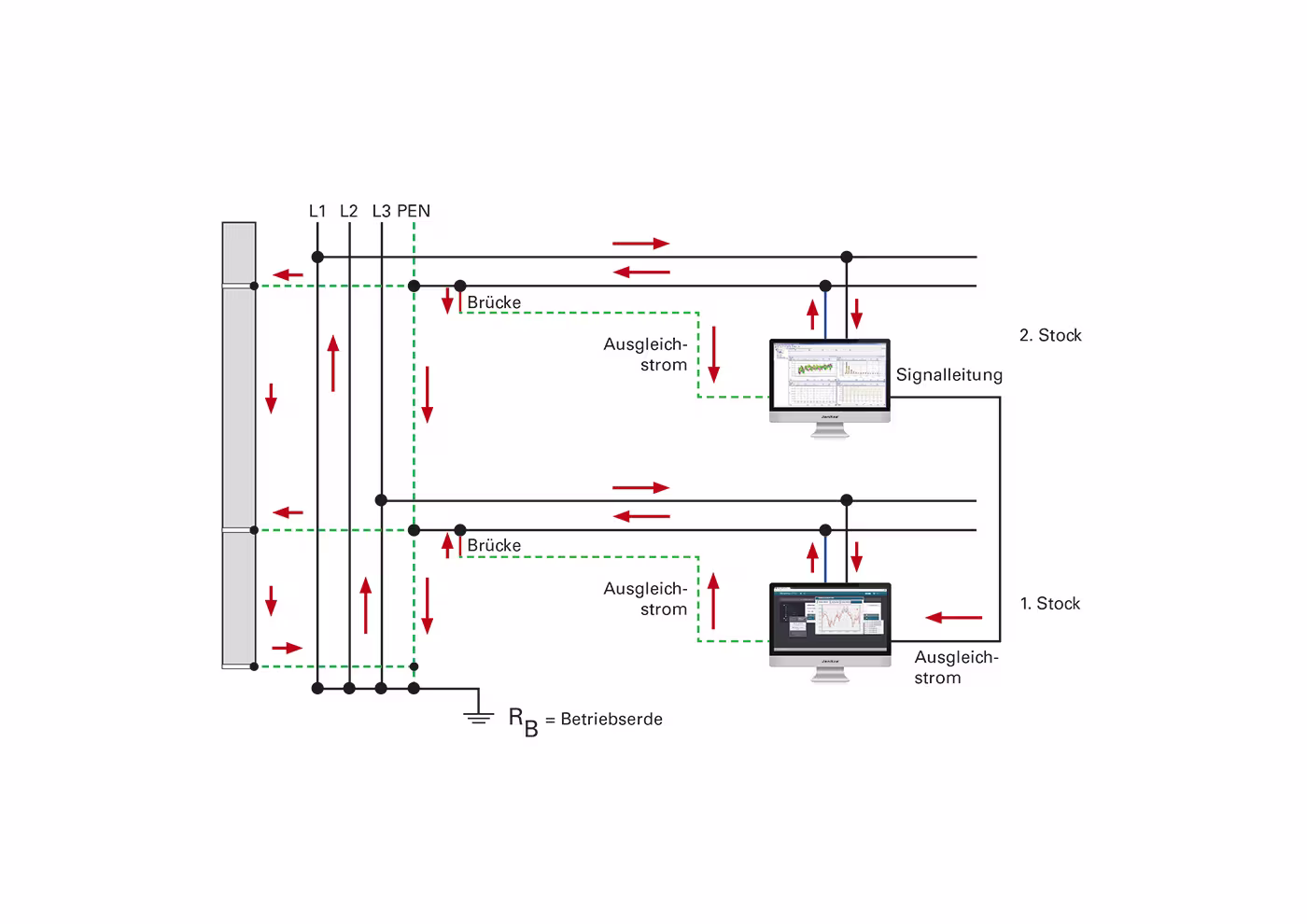
Connections between N and PE conductors result in "stray" operating currents being distributed via the PE system, data lines and all metal parts of the building. Because these currents are not balanced, they generate electromagnetic fields. The consequences are many types of disturbances in the electrical systems, EDP networks and piping systems of the building installation. Image 12 illustrates how the operating current is divided at the PEN bridge and can flow back via several paths, as a result of which the sum of the forward and return conductor current is no longer 0. This can result in the following faults:
- Changes in the operating behavior of frequency-dependent components (e.g. capacitors draw more current)
- Interference in data transmissions due to magnetic and inductive influences
- Transfer of lightning effects into the electrical system
- Corrosion on metal pipes
- Influencing people
Forward and return conductors, even in distribution systems, need to be arranged close together to minimize magnetic fields. At each node of a circuit, the sum of the currents must be zero to avoid residual currents. In addition, the subdistribution panel or circuit should be monitored with an RCM. The UMG 96RM-E is ideal for monitoring subdistribution panels or larger consumers.
Individual circuits in which residual current circuit breakers cannot be used for operational reasons can be monitored with the UMG 20CM. A reporting RCM combined with specialist personnel on site ensures maximum, alternative safety.
Neutral conductor and CGP
The neutral conductor (operating current return conductor) has become the most important conductor today. It must be treated like a phase conductor. To ensure that the grounding system remains "clean", the live N conductor must be positioned away from the PE conductor. No galvanic operating currents may flow via the grounding system, as these would cause inductive coupling. These measures must be taken to the supply source.
In the TN-S system, the N conductor only needs to be connected to the grounding system and monitored once, at a suitable point at the CGP (central grounding point from N to PE). Unwanted insulation faults or galvanic connections between N and PE are detected immediately by monitoring the CGP. Deviations are reported in good time and time dependencies are analyzed.
The UMG 512, for example, can be used to check whether the TN-S system is functioning correctly. It allows a holistic view of power quality and EMC. This even allows the initiating phase of a ground fault to be recorded and analyzed. The phase current then increases in parallel to the central grounding point current. The current on the CGP must always be considered in relation to the total power of the TN-S system. This means that, on the one hand, operational leakage currents are tolerated, but abnormal deviations on the CGP are reported by the RCM.
Summary and outlook
Future power supplies will have to meet increasingly stringent requirements, because power failures result in high costs and immense annoyance. Continuous RCM monitoring is becoming increasingly popular for highly available power supplies with high EMC requirements and also for preventive fire protection. To meet this trend, Janitza launched the new 20-channel UMG 20CM series in 2013 and will present two more products in 2014: the UMG 509 and UMG 512. The aim here is RCM monitoring of the power supply at all four levels (infeed [PCC], main distribution boards [transformer outlets], subdistribution panels, individual loads [e.g. server cabinets]).


Company portrait
JANITZA® ELECTRONICS GMBH
Janitza® electronics GmbH is a German company and has been operating in the field of manufacturing systems for efficient electricity use, energy measurement, and cost savings for 50 years. As a world-renowned manufacturer of grid monitoring and energy management devices, digital panel meters, power factor controllers, and compensation systems, the company stands for the highest quality standards and innovations. Products are manufactured using state-of-the-art production technology and the latest findings. Quality management at Janitza is an ongoing task (e.g., ISO 9001). Extensive know-how, expert consultation, and concept development right through to commissioning custom solutions fulfill the wishes and requirements of customers.